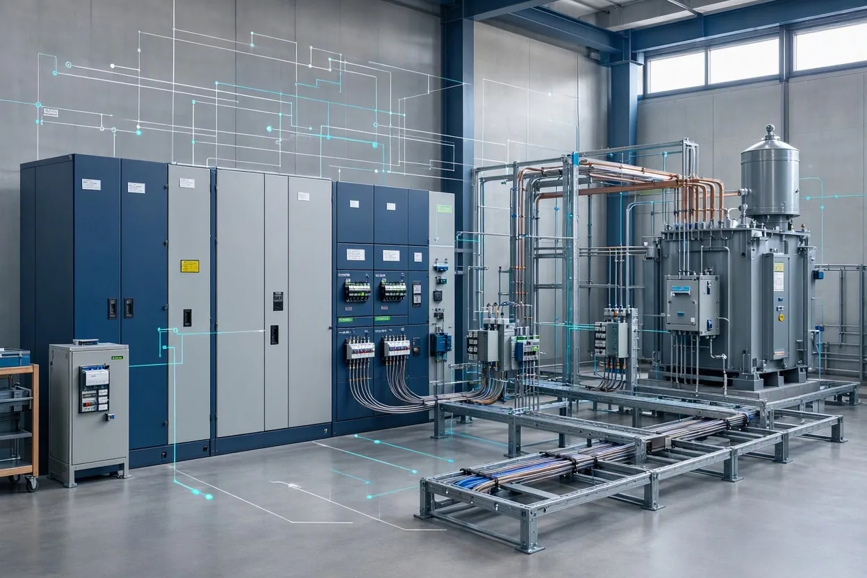
Stage 6 of 14 / Calculation
Build the cooling load and thermal boundary
Convert IT heat and in-boundary electrical losses into air and liquid duties, flow requirements and a cooling reserve.
- Advanced
- 14 stages
- 18 min
- Mission-critical electrical and thermal systems
After this stage you can
- Build design heat load from IT and in-boundary electrical losses.
- Calculate air and liquid flow and fan/pump power from explicit temperature differences.
- Check cooling capacity, reserve and topology against the design heat load.
The engineering
Cooling starts with heat, not with a chiller catalogue. The model adds IT peak and the electrical losses that sit inside the cooling boundary: UPS heat, PDU losses, transformer losses and cable losses. That total is the design heat load.
The air/liquid split is a design decision. Air-based cooling suits lower densities; direct-to-chip liquid cooling is used at high rack densities; hybrid designs split the duty. The model calculates air mass flow from Q = m cp dT, liquid flow from Q = rho cp dT, and fan/pump power from flow and pressure.
A cooling shortfall can force IT load reduction before electrical capacity is exhausted. The cooling unit count is checked against the selected topology and a reserve margin. The output is a thermal screening model, not a psychrometric coil selection or a CFD study.
EngiMetric / AI data-center workbench
One project, computed from rack to report
Loading the saved project state...
Preview screen. Inputs are saved in this browser only. Climate, grid, water and cost values are illustrative. Failed checks stay visible; a clean summary is not a stamped design and no Tier rating is claimed.
Your deliverable for this stage
A cooling load statement with air/liquid splits, flow and plant electrical demand.
Stage assumptions, limits and sources
Assumptions
- Air properties are evaluated at 1.15 kg/m3 and 1.005 kJ/kg/K; water at 4.186 kJ/kg/K.
- All IT and in-boundary electrical heat is rejected by the cooling system.
- Fan and pump power are facility loads and are not re-added to the cooling load.
Constraints
- Screening thermal model, not a coordinated cooling design.
Limitations
- No humidity control, economiser hours, coil model or part-load chiller curve.
- No pipe network, pressure-drop, CDU curve or refrigerant design.
- No CFD, acoustic or water-treatment design.
Review status
- Needs engineering review
- Professional review is required before publication or use as a design basis.
Sources
- Uptime Institute - Tier Standard overviewengineering org
- ASHRAE - Data Center Guidance and Datacom Seriesengineering org
- Open Compute Project - Data Center Facility projectengineering org
- NVIDIA - DGX SuperPOD reference architectureofficial docs
- U.S. Department of Energy - Data centers and serversgovernment
Stage progress is stored in this browser only. The explanation and every limit on this page remain readable with JavaScript disabled; the calculators need it to run.
Stage kind: Calculation / Journey: ai-data-center / Stage: cooling-load