Stage 4 of 14 / Calculation
Size the electrical infrastructure and losses
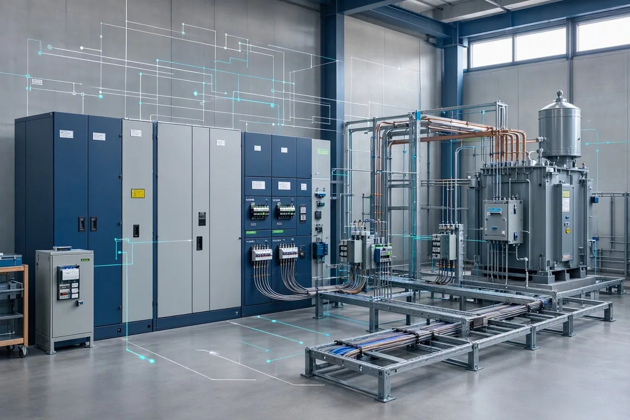
Convert concurrent IT peak and critical auxiliary load into UPS input, facility demand, transformer capacity, battery energy and generator capacity using explicit efficiencies and loading targets.
- Advanced
- 14 stages
- 22 min
- Mission-critical electrical and thermal systems
After this stage you can
- Trace IT load through UPS, PDU, transformer and cable losses to facility demand.
- Check transformer, UPS, battery and generator sizing against loading targets and topology rules.
- Distinguish real power, apparent power, installed capacity and usable capacity.
The engineering
The electrical model is an energy balance. IT peak and UPS-backed critical auxiliary load create UPS input after UPS efficiency. PDU losses, non-critical auxiliary load and cooling power are added upstream. Transformer and cable losses are applied to that throughput. The result is the facility demand at the utility connection.
Cooling power is itself an electrical load, and electrical losses are a cooling load. The model resolves this loop by fixed-point iteration. If it does not converge, the report says so instead of hiding an unstable result.
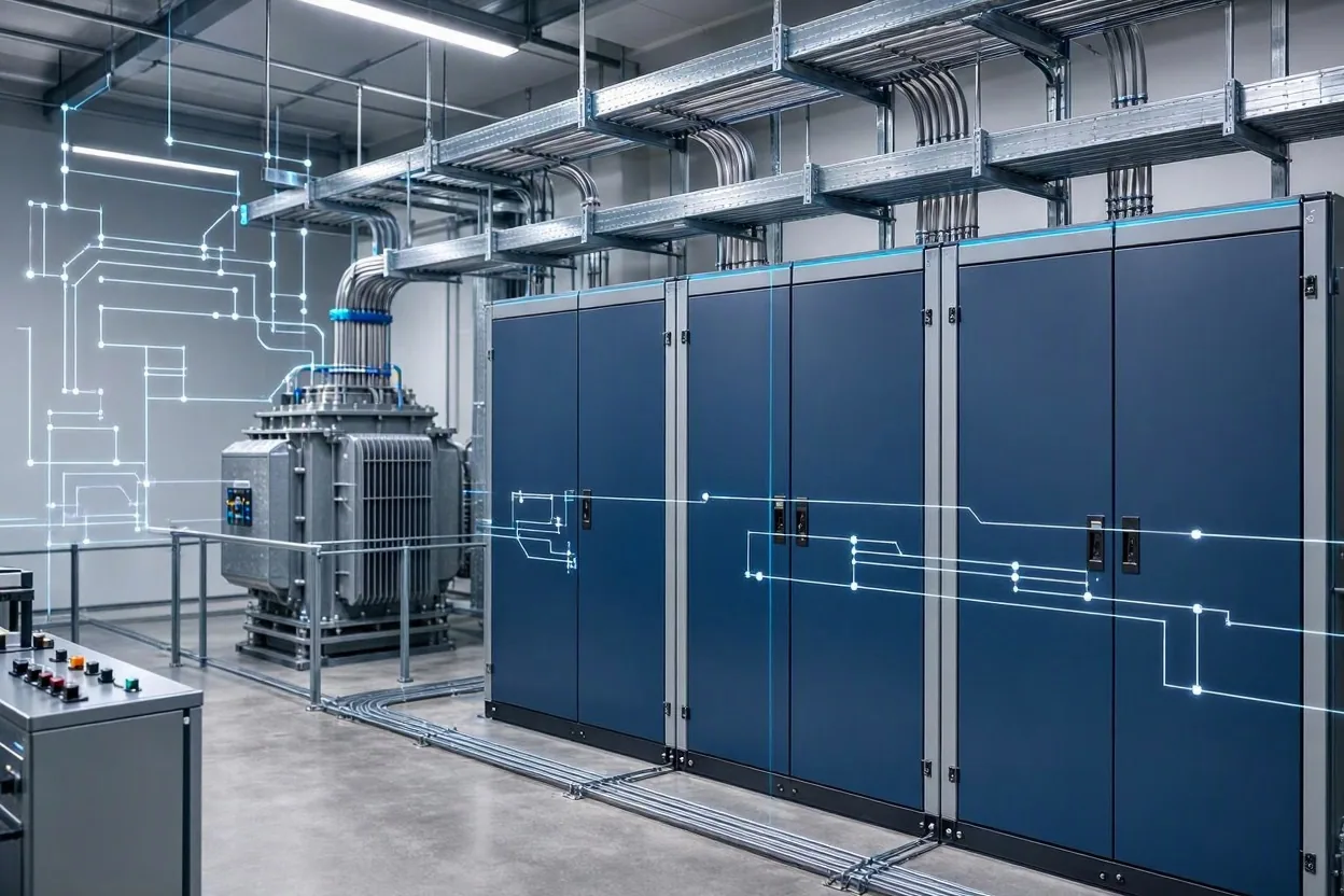
Equipment is not sized by dividing load by nameplate rating. Each block uses a loading target and a topology requirement: N, N+1 or 2N. Battery energy uses autonomy, depth of discharge and discharge efficiency. Generator rating includes a margin and a step-load screening check. Short-circuit, protection coordination, arc-flash and conductor sizing remain outside the implemented scope.
EngiMetric / AI data-center workbench
One project, computed from rack to report
Loading the saved project state...
Preview screen. Inputs are saved in this browser only. Climate, grid, water and cost values are illustrative. Failed checks stay visible; a clean summary is not a stamped design and no Tier rating is claimed.
Your deliverable for this stage
An electrical load summary, equipment schedule and failed-check list for the selected topology.
Stage assumptions, limits and sources
Assumptions
- Cooling power is a facility load; only IT and critical auxiliary load are UPS-backed.
- Transformer and cable losses are proportional to throughput.
- Battery energy is sized from UPS load, autonomy, depth of discharge and efficiency.
Constraints
- Preliminary equipment schedule only; not a procurement bill of quantities.
Limitations
- No short-circuit, protection-coordination, arc-flash or conductor-sizing study.
- No harmonics, inrush, motor-starting or generator transient-stability model.
- No utility interconnection or transformer inrush design.
Review status
- Needs engineering review
- Professional review is required before publication or use as a design basis.
Sources
- Uptime Institute - Tier Standard overviewengineering org
- ASHRAE - Data Center Guidance and Datacom Seriesengineering org
- Open Compute Project - Data Center Facility projectengineering org
- NVIDIA - DGX SuperPOD reference architectureofficial docs
- U.S. Department of Energy - Data centers and serversgovernment
Stage progress is stored in this browser only. The explanation and every limit on this page remain readable with JavaScript disabled; the calculators need it to run.
Stage kind: Calculation / Journey: ai-data-center / Stage: electrical-infrastructure